05 April 2016
No. 4
Making a 3d scanner for under $20
At this Spring's HackPrinceton, my friend AK and I built a fast and efficient 3d scanner out of spare parts. I think it's very cool.
Both the project submission and the source code are online.
How does it work?
For measurement, we used a reflective IR LED. More detail on this later, but basically I'm using it here as a close-range distance measurement tool.
In order to measure a 3d surface, two other components come into play, each adding a separate dimension to the scan. The first is a vertical shaft which raises and lowers the reflective IR LED. The second is a DC motor, which rotates the scanned object, allowing the scanner to measure its sides.
Scan accuracy
You're probably wondering how accurate this project's scans actually were. It's literally a ten-cent RIR LED on a stick, held together by cardboard.
I wondered that too, as we were building it. I hadn't seen examples of reflective IR LEDs being used for measuring distance before. And even though it showed promising results when I tested it before starting, I couldn't be sure how accurate it was, given that the data was definitely not a linear function of distance.
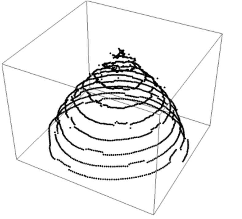
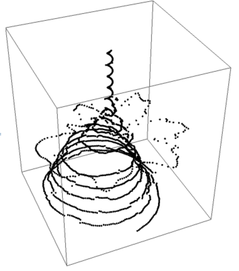
As it turns out, the scans were pretty darn accurate. In fact they were so clean, we had a judge doubt that the data was live. He waved his hand in between to see, and you can see the results above (middle picture, compared to the original on left).
Is it really under $20?
Yup. I source most of my electronics from Aliexpress, so that helps. Here's the breakdown:
- Reflective IR LED - 10 cents
- DC motor - $3
- Breadboard - $3
- Continuous rotation servo - $7
- Arduino clone - $3 to $10
- USB A Male <-> USB B Male adapter - Free (usually included with the Arduino, even cheap ones)
- Plastic gears - $3 for a bag, probably $0.20 for parts used
- Cardboard - Free
- Electrical tape, wires, resistors - around $2 worth of parts
And this isn't even pricing at scale, or with efficient use of parts (e.g. using a PCB instead of breadboard + wires).
Ideation process
Akhilesh and I flew into Philadelphia early, so we went to a Public Library to kill time before the hackathon started. He goes to the bathroom, and comes out wondering how hard it'd be to scan his poop. I look at my kit and see if we have the parts. And here we are.
Prototype process
After some fairly basic tests, I decided that a Reflective IR LED was probably our best bet as a scanner. Our alternative was an ultrasonic rangefinder, and I didn't think it'd have enough granularity at low distances to work as a close-range 3d scanner.
Next, we needed to move the object or the scanner such that the entire object could be scanned. We focused on the vertical dimension first. I tried using a pulley-like system with a DC motor, and of course without a smooth pulley it'd occasionally slow or snag, and we couldn't get a consistent speed.
Looking for an alternative, I looked in my tackle box of hardware and found a rack to use in a rack and pinion gearing, and that actually worked perfectly, once we secured it into place. I attached the RIR LED, and also put a cylinder of electrical tape on it to try and make it pick up less noise, which actually worked pretty well.
Then we tried making a flat base and attaching it to a dc motor. We first tried taping a few pieces of cardboard together and using the hole in a zip tie to attach it to the dc motor and hold it in place. It didn't work; it ended up too wobbly to actually get any decent measurements on, though.
We were lucky, though: the dc motor I used had basically the exact same diameter as one of the gears in the gear set, so we were able to tape cardboard circles to the gear in order to provide a larger base, and this gave us less wobble than our earlier design.
Once we got this working, we also needed to hold the rack and pinion together using a bunch of zip ties, cardboard, and duct tape. The motor also broke apart a couple times, requiring the metal inside to be repositioned. And of course, we needed to calibrate everything, to get near-usable results!
Calibration process
In this process, we figured out a function to convert the Reflective IR LED's raw analog output to units of distance. We also figured out the function to get vertical distance (vertical scanner movement) and degrees of rotation (horizontal base rotation) as a function of time.
Figuring out position of the z-axis was simple, we just measured the distance/time to get the speed of the motor when moving vertically, which given the initial value of 0 (measuring starting at the object's base), gives the z position as a function of time.
To find the angle of rotation, I measured the length of time it took for 10 rotations (to reduce error from starting/stopping time) and divided by 10.
To find the distance from the object to the scanner, we needed to fit the data given by the reflective IR LEDs. And for that we needed some data points to get a curve best fit. Using Chrome dev tools as a substitute for a ruler, I recorded the scanner's analog output values, while moving a piece of cardboard away, centimeter by centimeter.
With this data, we were able to estimate the function best fit using Wolfram alpha:
$$$ f(x) = -600 + \frac{19169 \times x}{30} + \frac{30433 x^2}{360} - \frac{1751 x^3}{16} + \frac{4009 x^4}{144} - \frac{727 x^5}{240} + \frac{89 x^6}{720} $$$
Glad we didn't have to calculate that by hand. Unfortunately Wolfram didn't give us the inverse, which we needed (in a scan, we have raw analog values and want estimated distance). So I just plugged in the range of input values, which is a limited range of ints (0-2048), and made a lookup table instead.
Combining these functions, we were able to determine y/z coordinates given distance and time. (Remember, our scanner rotates and moves up at the same time, so it's moving in a spiral shape.)
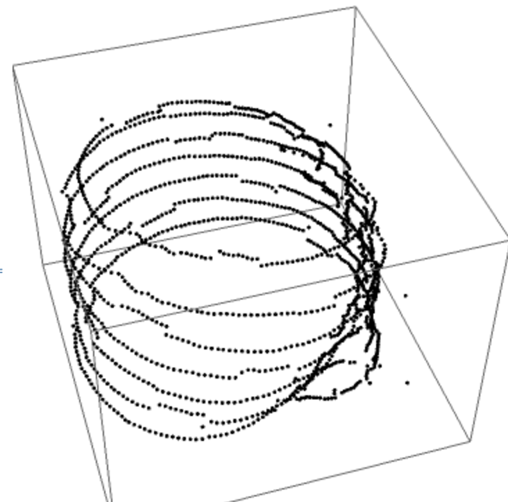
And with this, we could generate point clouds (seen above in earlier sections)! From this, you can estimate the shape of the object, and generate a STL file to send to your 3d printer, in order to print the object you just scanned!
Want to build it yourself?
Caveats
Want to build this on your own? It's very cool, and very cheap! But if you're planning on using it for anything serious, note a couple caveats:
You'll probably need 3d-printed parts for it to be calibrated well. (Though it's fun project to make by hand though, and the experience and results were pretty rewarding.) It's also not that great at scanning anything too glossy (shiny plastic/metal).
Details you might find useful
All data is passed via USB from the Arduino to the laptop, where all of the processing is done in Node. It's much faster that way, and you can do whatever you want with it from there.
Data is sent from the Node instance to the Wolfram notebook through.... the wondrous OS X clipboard (last minute features, what can I say). It takes a long time for Wolfram Notebook to graph the data, but I think it's just slow frontend javascript, not optimized for large datasets. It might be faster on other software.
I don't have any good pictures of the circuit, but the only complicated part is wiring the Reflective IR LEDs, which you can do like this:
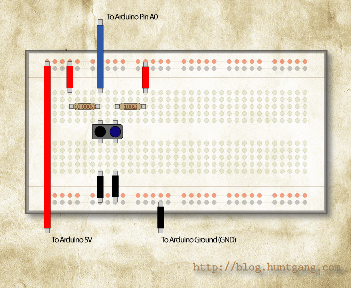
Thankfully no signal amplifiers are needed (I didn't have any), and the wiring for the servos and dc motor are also pretty standard. Have fun!